Over the years, I had 4 sailboats before Celia and I bought our Gemini. They've had various levels of complexity for managing electrical needs and each was more complicated than the prior. Probably pretty much the case for most boat owners.
All that work on QUETZAL reaped some reward, though. The portion of the electrical system on QUETZAL that I did finish was so successful I knew I wouldn't be happy with anything less down the road. So when Celia and I decided to buy our Gemini, I had a good idea what to suggest to make a solid system. And we had the advantage of year-2000 technology for greater functionality and reliability than I saw on the earlier boats.
You have to have a plan, of course, otherwise you won't know when you're done. So we put together some ideas about where we were going with the basic electrical system. We needed this in place before we could add goodies to the boat. After doing estimates of current consumption for standard equipment and items likely to be added, we created the Goals in the table below. Then we filled in what we thought or knew the Gemini to have. The Goosebumps column is what we have today. The numbers in () refer to notes below the table. Keep in mind that this was put together in 2001, so there may be better choices today.
| System |
Goal |
Gemini |
Goosebumps |
| Distribution | Breaker panels for circuits |
1-AC, 2-DC panels Several circuits are limited for adding accessories |
Same DC panels, AC panel modified Upgrading wire size as we go |
| AC Power | 30 A dockside 1,000 V-A min underway |
30 A dockside 0 V-A underway |
30 A dockside 1,500 V-A inverter (2) |
| Batteries (5) | 400 AHr deep cycle house + |
195 AHr combined house & start flooded cell | 400 AHr combined house & start AGM (absorbed glass mat) |
| Charging: | |||
| Dockside | 40 A multi-stage charger (10% of battery AHr cap.) | None provided | 70 A multi-stage (2) |
| Alternator | 100 A, external regulator (25% of battery AHr cap.) | 50 A internal regulator | 75 A, external regulator (1) |
| Auxiliary | 50 AHr recovery for 6 Hr daylight (about 8 A avg) (3) | Optional | 2-80 W Kyocera panels provide about 6 A avg. (3,4) |
| Monitor | Measure V, A & AHrs on 2 banks | n/a | Link 2000-R measures these values (1) |
So that was our plan. The paragraphs below fill in some details of what we installed or changed to fit this plan. Hopefully it will help others avoid some of the pitfalls or make decisions for their own boats that better fill their needs. Keep in mind that I'm not an expert on marine electrical systems, so this represents what I'm comfortable with for my own needs.
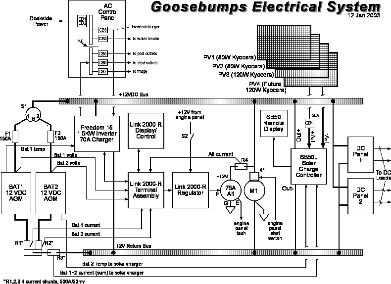
This is a block diagram of the electrical system as it currently is configured (hopefully with not too many errors!).
This is the control panel(s) and all the wiring in the boat. Fortunately, the Gemini takes advantage of the evolutionary changes that have happened in the boating industry. While there are a number of things I might have done differently (larger gauge wire, wires in conduits, etc.), what they have designed for the Gemini is better than anything I've had on earlier production boats.
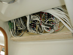 After
a few weeks poking in all the corners and looking at the wiring I could see
that it was on the minimal edge of what I'd have chosen. Unfortunately the wire
harness is installed before the liner is bonded to the hull, so pulling in new
wires using the old ones is more than a small challenge. However, Tony left
a few places where additional wires can be routed and we've slowly been finding
them.
After
a few weeks poking in all the corners and looking at the wiring I could see
that it was on the minimal edge of what I'd have chosen. Unfortunately the wire
harness is installed before the liner is bonded to the hull, so pulling in new
wires using the old ones is more than a small challenge. However, Tony left
a few places where additional wires can be routed and we've slowly been finding
them.
I've left the 3 power panels unchanged save one mod: we cut the AC panel buss bar to separate the Main, Water Heater and Battery Charger breakers from the other breakers that are served by the inverter. We had to split the buss bar to eliminate the possibility of the inverter output supplying power back to the battery charger which would cause destructive feedback in the inverter/charger.
We did add a circuit breaker and some wires to the system to accommodate our bigger batteries, current shunts and some new equipment:
Later we'll add some large wire from the batteries to the port bow area to supply a deck wash down pump and possibly a windlass. We also see a need for additional 12 VDC outlets for the portable refer we added and for running our computers; both currently need the inverter underway.
This part was pretty easy. We opted for the Heart Interface Freedom 15-12. It supplies 120 VAC at 60 Hz (pseudo-sine wave). We'd love to have a Trace or one of the other true sine wave inverters, but weight and cost got in the way. And having a combined inverter and charger reduced the real estate needed for mounting everything.
Btw, Heart Interface was bought by Xantrex along with Trace Engineering, StatPower and a few others. Xantrex is in a position to control most of the marine power supply market.
The Gemini is wired for 30 amp dockside AC power at the factory. The inverter is designed to have all the AC load pass through it to the AC control panel. All we had to do was connect the input of the inverter to its breaker and the output of the inverter to the AC breakers on the AC power panel (recall that we broke the AC power panel buss into 2 separate busses). This way the inverter can sense when dockside power drops out and substitute the inverter output to keep everything running. Similarly when dockside power returns, the inverter senses its presence, removes the inverter output and substitutes dockside power in its place.
One of the quirky things that happens when you charge batteries with a large capacity charger is it can use up a lot of the available dockside power. If the batteries are really low, that can mean using 15 amps of AC to supply the 70-80 amps at 12 VDC. On a Gemini, that's 50% of the available power from the dock. If you're trying to run an air conditioner and one or 2 other things at the same time, pop goes the breaker! To minimize the conflict, the Freedom allows the user to select how to share power between charging and the rest of the AC loads. If the charger gets to that limit and the rest of the boat needs some power too, the Freedom starts limiting the charger output so it stays within its power budget.
As mentioned above, we took the precaution of breaking the buss in the AC panel into 2 separate busses to preclude trying to power the battery charger with its own inverter output. The Freedom manual explains this pretty well and we've had no ugly surprises how everything works together. Breaking the buss also gave us the opportunity to keep the inverter from powering the water heater, but we can run the refrigerator if we absolutely have to(not an efficient use of battery power!).
All in all, the Freedom has been a set-it-and-forget-it device. We haven't
had any problem with other devices operating with pseudo-sine wave inverter
power except one: the cheap Radio Shack speakers we bought for our TV/VCR buzz
like crazy when the inverter is running. Of course, these speakers buzz on dockside
power too... went too cheap here I'm afraid! Everything else, from microwave
to computer to vacuum cleaner, has operated without a hitch.
[5/2003: we found the charger for our Braun tooth brush can't handle the
inverter wave form. 2 of these chargers died when we switched form shore power
to inverter (we're slow learners!). The toothbrush is fine and a replacement
charger is available from Braun for $18.]
If there were a way to install 4-L16 batteries in the Gemini without sinking the port hull further below the design waterline, we might have done it. In fact, I'd have settled for just 2! But Goosebumps has a real estate problem caused by placing the auxiliary heater just aft of the port centerboard case. In order to water the batteries, I would have had to cut access holes in the bottom of the nav station storage compartment and the shelf just below it to reach the top of the batteries. Since that's where the heater and the inverter/charger live, it isn't really an option.
Initially we settled on 4-GC2 (GC = golf cart) 6 VDC flooded cell batteries from Deka (Trojan T-105 batteries would probably also have fit). Contrary to current thinking in the cruiser press, we arranged these 4 batteries in 2-12 VDC banks for a total of 440 AHr or 220 AHr usable (popular authors recommend a single bank of paralleled batteries; I disagree with this approach). At the installation time I thought had enough space above the batteries to be able to water them if I used mirrors & a flashlight and fed water from a bulb with a small diameter hose attached. Didn't work. At all.
Then Fran Tschida on VOORTREKKER III told me about a method he developed to water the batteries blind using a voltmeter connected to a piece of wire suspended a measured distance above the electrolyte. He uses a tiny model airplane fuel-priming bulb to add the water to each cell until he gets a reading on the voltmeter. Cool. However, a couple acid burns on clothes and my arm dissuaded me because our least accessible batteries leaked some acid around the terminals. I just didn't want to fight watering the batteries anymore, so...
After just 18-months of good performance from them, we replaced the flooded cell Dekas with 4-8AGC2 AGM (absorbed glass mat) sealed batteries from MK Battery (we purchased them through Batterystuff.com in Oregon). Other manufacturers offer 220 AHr rated versions in this size, but ours 200 AHr per bank for 400 AHr total (200 AHr usable). Most of the difference (200 AHr vs. 220 AHr) appears to be in the temperature at which batteries are rated. Perhaps a better choice might have been AGMs from Concorde, but they were described as suited for "fixed solar system use" which sounded like they want a benign environment. A sailboat underway is anything but benign!
We just finished installing the AGMs (December 2002) and can't
really comment on performance yet. Btw, East Penn owns both Deka and MK Battery.
[3/2003 update: the Link 2000 has recalculated the CEF (charge efficiency
factor) enough times now that we can see it's around 95-98% vs. 90% industry
average. We also see that there's a very slight difference in the charge characteristics
of the 2 banks which causes one bank to never reach full charge. This is the
reason for isolating batteries into separate banks.]
[5/2003: couldn't be happier that we made the change from flooded cell
to AGM batteries. CEF is 98% for both battery banks. You definitely temp sensors
integrated with any chargers!]
Our charging system consists of 3 parts:
To do it right, each of these charging systems must provide a charging profile (the transition voltage from bulk to acceptance and from acceptance to float over the battery operating temperasture range) that matches our AGM batteries. But of course, nothing is as it seems as I'll describe later.
Brand-familiarity and price certainly played a large part in our choices, so our selection process was flawed from the git-go. I relied a lot on past experience and did a lot of reading on the internet. Something that popped out very early was that Heart Interface had a very well integrated system and, to my surprise, they had bought the old Cruising Equipment Co. So the concept that evolved from my favorite old Tri-& QuadCycle regulators found its way into the Link 2000-R. This was then integrated with Heart Interface's Freedom inverter/chargers.
Unfortunately, Heart Interface charge regulation development stops short of supporting solar and wind power charging. At least it solves the initial concerns for alternator & dockside charging. It also measures everything going in or out of the battery no matter the source(s). So even though the Link 2000-R can't control a wind generator or a solar panel, it does measure the current into the battery that these sources may provide.
Before we left California I bought the big pieces we needed: a Freedom 15 inverter/charger and a Link 2000R monitor with alternator regulator (the R suffix). The BalMar alternator we bought through Peter Kennedy Yacht Services in Annapolis. Btw, Peter did the installation of our radar and our SSB and did well by us.
This job is handled by the Freedom 15-12. Ours came with a temperature sensor which adjusts the charger output as temperature changes (resolution is in decades of the Fahrenheit scale). The charger supports 4 different battery charging profiles.
With our first batteries we used the flooded cell profile without making any effort to compare the battery makers charging requirements with what the Freedom provided. When we changed to the AGM batteries we expected to use the AGM profile. As I learned, though, there are AGM batteries and there are AGM batteries: you can't presume that they all are charged with the exact same parameters.
The details came out after I finished installing the new batteries and tried to adjust the Link 2000-R/Freedom settings for the new AGMs. Our Freedom, which was designed many years ahead of our batteries, doesn't have an AGM profile which matches our batteries within the tolerance band MK Battery recommends.
The names of the profiles don't mean much... they could have called them A, B, C & D. It's up to the user or installer to look at the table in the Freedom manual that describes the various charging voltages and compare that info with what the battery maker says their battery wants to see. I found if I could use the gel cell profile for bulk and acceptance levels, then switched to lead acid for float, things were pretty close. Of course that's not realistic. The standard flooded cell profile comes pretty close at temperatures from 50-80 degrees F, so that's where we left it.
If there's a fault with the Freedom charger, I'd have to say
it's the inability for users to set their own charging profile.
[5/2003: we found that the batteries were often above 90 degrees F as
we moved from April into May making the standard profiles unsuitable for our
use.]
This job is done by the regulator supplied with the Link 2000-R controlling the 75 amp BalMar alternator (which I'm told is originally manufactured by Lestek). Unlike a conventional automotive alternator plus regulator, this system performs the charge duties in 3 stages (or phases or steps or whatever).
These 3 stages (or phases or steps or whatever...) are collectively referred to as multi-stage or "smart" charging because they are aimed at getting the most charge into the battery in the least amount of time without causing damaging overheating or gassing of the battery. The result is much longer life from a battery. On QUETZAL, the L-16s were still very near their full capacity after 10 years. There's no reason to expect anything less from the current level of charging technology.
The 4th cycle is the Equalization stage. Repeated cycling of a deep cycle battery leaves small amounts of lead sulfate crystals on the plates. It happens because it's very difficult to get 100% of the charge back into the battery, yet that's what you have to do to get rid of the lead sulfate. There are devices on the market called de-sulfators which are supposed to fix the problem, but lacking that, the traditional method is to charge the battery for few hours at higher than normal voltages. During equalization, battery voltage may go as high as 15-16 VDC causing the battery to gas heavily as it gives up sulfate crystals and the lost capacity is restored. Equalization is supposed to be done on only flooded cell batteries and never on gel or AGM batteries because gassing causes the sealed cells (2 psi max) to vent hydrogen & oxygen. Once the gasses are lost they're no longer available to be recovered in the electrolyte.
That said, one of the charging modes recommended by MK Battery for their AGM sounds very much like equalization. They recommend finishing the charging stage (Acceptance) with a constant current charge or 1-2 amps per 100 AHr of capacity. The safety shut off is a limiting voltage of 16.8 VDC. Everything I've read calls that Equalization. Before we do this on a daily basis I'd need an explanation from MK Battery.
As you can see in the table notes above, we initially thought that 2-80 watt Kyocera panels would provide sufficient power for our needs. Amazing how wrong we were.
We seem to be real power hogs: watching TV, using the SSB for e-Mail & weather, lights to read by, power for the computers, anchor light, etc. adds up to an exorbitant power bill! On a really good day of solar charging at anchor we recovered about 40 AHrs. After an evening of very light usage (fix dinner, plan the next days route on the computer, read a little, get to bed early) we recovered as much as 75% which is not too bad. That means running the engine every 8th day to top up the batteries. But if we gathered radio mail and watched a little TV, we hit 80 AHrs for a single evening. Then if the next day is at all cloudy, we might put back about 15 AHrs leaving a deficit of 65 AHrs. And that means running the engine every 2 or 3 days. Conservation was (is!) in order, but after several attempts it was pretty clear that we weren't going to reduce the daily usage by a significant amount. Btw, replacing the incandescent bulb of the anchor light with an LED light source from Deep Creek Designs can save about 12 AHrs per nite! Plus the slightly blue color of this light makes your boat easy to spot in a crowded anchorage.
So with the power useage we have and wanting to minimize engine run-time, we decided to increase our solar charging capacity. I'd thought wind charging would be a good choice, but several cruisers lobbied pretty hard to avoid that approach. We've decided to expand our solar array to provide more power and only if that still falls short will we look to a wind generator, probably a unit that can be suspended from the rigging while at anchor.
To increase the capacity of our solar array, we went after 3 things:
More Panels. Kyocera makes a 120 watt panel that fits along the lifelines and most importantly has performance characteristics that match the voltage output of our two 80 watt Kyoceras. Using a mounting kit from e-marine-inc.com, we attached the panel to a 1" stainless tube that attaches to the lifeline stanchions. Really a very simple attachment. We'll do this in steps, adding a second 120 watt panel to the starboard side later if necessary.
Controlling Panels. A lot has happened recently in the way of charging batteries with a solar array. I learned about the current crop of regulators from friends cruising Australia & New Zealand on their Seawind 1000 KATIEKAT. Their charge regulator is apparently Aussie-built and charges, keeps track of AHrs and automatically equalizes the battery too. Pretty cool stuff and a significant improvement over our simple on/off relay controller.
Armed with that insight, I went looking on the internet. I found there's a range of regulators that use a DC-DC converter to manage battery charging. They refer to it as pulse width modulation (PWM). These devices are so sophisticated they're no longer called regulators. Today they're called charge controllers and can regulate the array output, divert power so that they can control both solar arrays and wind power, or do load control. They're made by companies like Morningstar, RV Power Products and Trace Engineering (now Xantrex).
The Trace charge controller has a lot of impressive features especially if you add a wind generator to the mix. However, we settled on a unit from RV Power Products units, the Solar Boost 50, which had the same capabilities plus a couple additional features:
The SB50 permits adjusting every charge parameter needed to match nearly any battery used on a boat. But the most interesting feature is it's ability to load the solar array at its maximum-power voltage.
Our 3 solar panels want to operate at somewhere around 16.9 volts to provide their maximum 280 watts combined power. Our older regulator simply connected the batteries to the array using a relay. This forced the panels to operate at the discharged voltage of the battery, say 12.0 volts. At 12.0 volts, the panel current will be higher, but the product of current * voltage (panel power) can be substantially less for the same amount of light... as much as 38% below its maximum power at low outside temperature when limited to this voltage.
RV Power Products approach for the SB50 is to separate the charging function from the regulation function. They load the array at the proper output voltage to get maximum power from the panels, then, using PWM, they charge the battery at the maximum current they can supply up to the setable voltage limit (Acceptance level). Charging is held at this constant voltage until the current drops to the setable limit of X% of battery capacity, in our case about 2 amps for a single 200 AHr battery bank (we purposely set the charging systems for a single battery bank, not for charging with the 2 banks paralleled).
An added benefit of the SB50 charge control design is that you can connect a pair of panels in series as a 24 VDC array. With the internal jumpers set properly, the SB50 will charge the battery at the parameters for a 12 VDC battery while maintaining the solar panels at the optimum voltage to produce maximum power at the combined 24 volts. This is really beneficial because the losses from voltage drop in the wires is 75% less. Very nice. If we add a second 120 watt solar panel we will very likely connect the panels as 2-24 VDC arrays of 160 watts and 240 watts. For the time being we are connected as a single 12 VDC, 280 watt array operating at 16.9 VDC and charging at 14.4 VDC or less.
 We
found space for the SB50 on the door of the hanging locker. This isn't
a small, lightweight unit! But the installation is fairly clean with a separate
50 amp circuit breaker mounted on the inside of the door so it won't be inadvertently
tripped by the crew.
We
found space for the SB50 on the door of the hanging locker. This isn't
a small, lightweight unit! But the installation is fairly clean with a separate
50 amp circuit breaker mounted on the inside of the door so it won't be inadvertently
tripped by the crew.
And the controller seems to work as advertised. On a cloudy day at outside
January temperature of 75 degrees F in Key West, we've seen numbers like
3.8
amps out of the solar panels and 4.2 amps into the batteries. That's a boost
of about 11%. On a cooler day we saw as much as 15% current boost. In chilly
Chesapeake Bay winters, the numbers ought to be significantly better since
the array can operate at an even higher voltage. (Photovoltaic array voltage
raises with a drop in operating temperature.) When the temps get up above
85 degrees, however, we don't see any current boost at all. Even so, the
charging profile is so much better matched to our batteries than all but
the Trace Engineering unit that we're happy campers.
[5/2003: the SB50 performance is incredible and I highly recommend their
use provided you follow careful installation guidelines that will minimize
line loss and get rid of heat.]
I mentioned earlier that we replaced the 14 AWG solar panel wires pre-installed on Geminis with 6 AWG wires. This dropped our line losses to about 1/16th of what we had with the 14 AWG (circular mils of copper roughly doubles every time wire gauge increases by 2, e.g. 12 AWG has twice the copper of 14 AWG). I wish I could offer comparison numbers to prove it wasn't wasted effort, but I can't... it's all on paper.
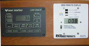
There may be other choices, but once I saw the Link 2000-R from Heart Interface and understood its capability I stopped looking. This compact microprocessor controlled system does all the measuring we need for our DC power system. It also controls charging with either the alternator and dockside charging systems.
Several pieces are included with the Link 2000-R:
The Link 2000-R display shows voltage, current and AHr capacity if each battery bank; the stored data the Link uses to compute each battery's charge efficiency factor (used to measure AHrs recovered through charging); capacity remaining for each battery; alternator output current (when it's running); and present charger and inverter on/off settings. Really a very complete system for managing a boats power system.
And now that the SB50 charge controller is installed, the monitor system is expanded by the addition of a display for the SB50. The display shows
Just like the Freedom inverter/charger, the SB50 knows it's ready to switch from Acceptance phase to Float when the current drops to a specific value. But if there are loads being used at the time charging is going on, then the SB50 doesn't know how much current is going to the batteries and how much to the load. To eliminate this ambiguity RV Power Products designed the SB50 to accept current data from an external shunt. We could have used the current shunts that were installed for the Link 2000-R without causing an error, but unfortunately the Link uses a dual shunt (one for each battery bank) and the SB50 only has a single input for measuring current. Btw, the SB50 displays the current from its internal current shunt, not the external shunt.
 Watching
the 2 displays of the Link and the SB50 is entertaining enough to replace
TV. Of course, I'm entertained for hours with a smooth rock and a piece of
string, so you may not be equally impressed. Celia wasn't! :-)
Watching
the 2 displays of the Link and the SB50 is entertaining enough to replace
TV. Of course, I'm entertained for hours with a smooth rock and a piece of
string, so you may not be equally impressed. Celia wasn't! :-)
[5/2003: the SB50 worked flawlessly. What we found, though, was that we
need more charging capacity from either another 120 watt panel or (and?) a
wind generator, probably rigging mounted.]
There you have it. A whole lot more than you ever wanted to know about the electrical system on Goosebumps. I doubt this page will get many hits, but at the very least it helps me to document what we've done to prep the boat for adding electronics and accessories for cruising.